LAB 5 - Open Loop Control
Wiring
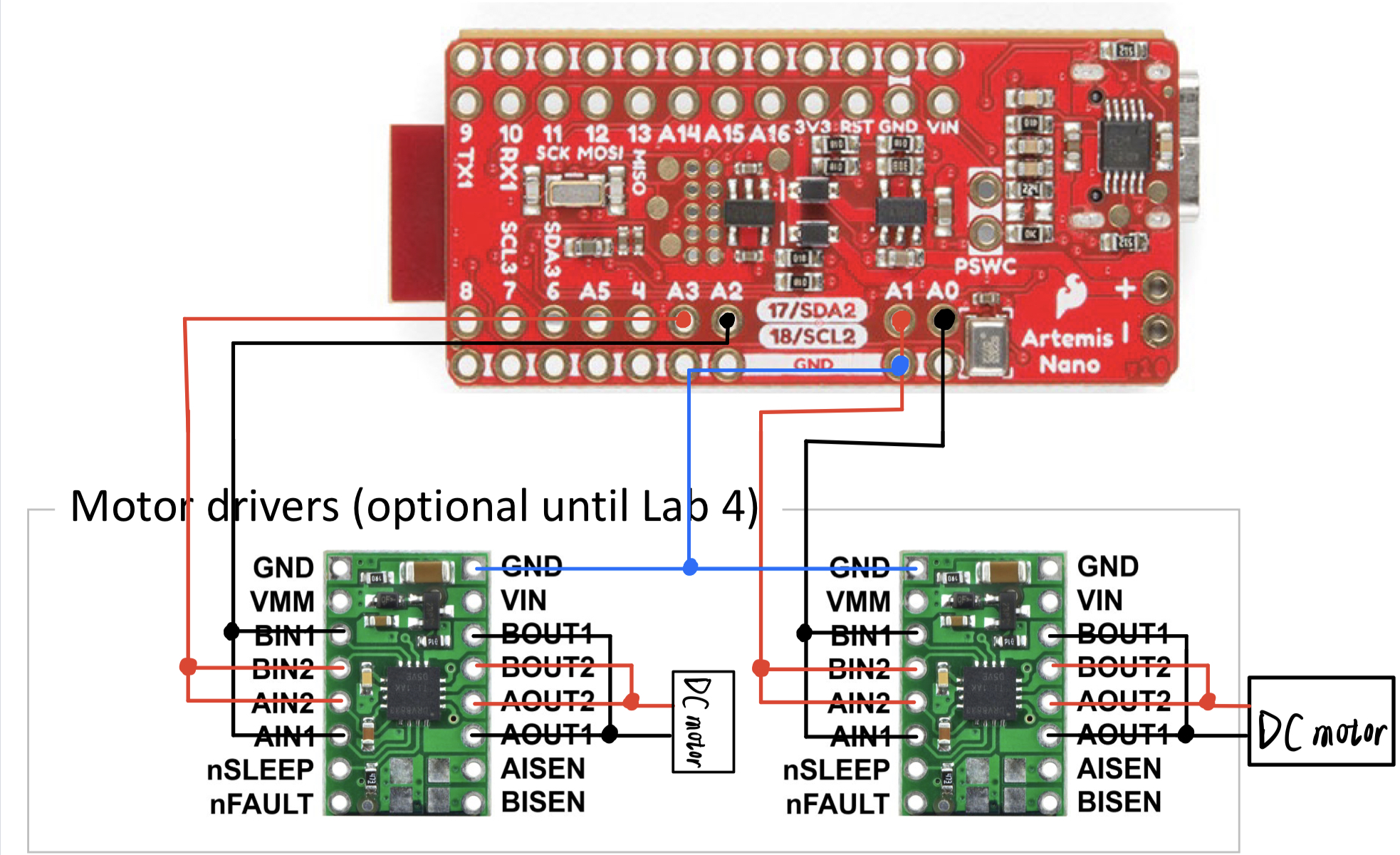
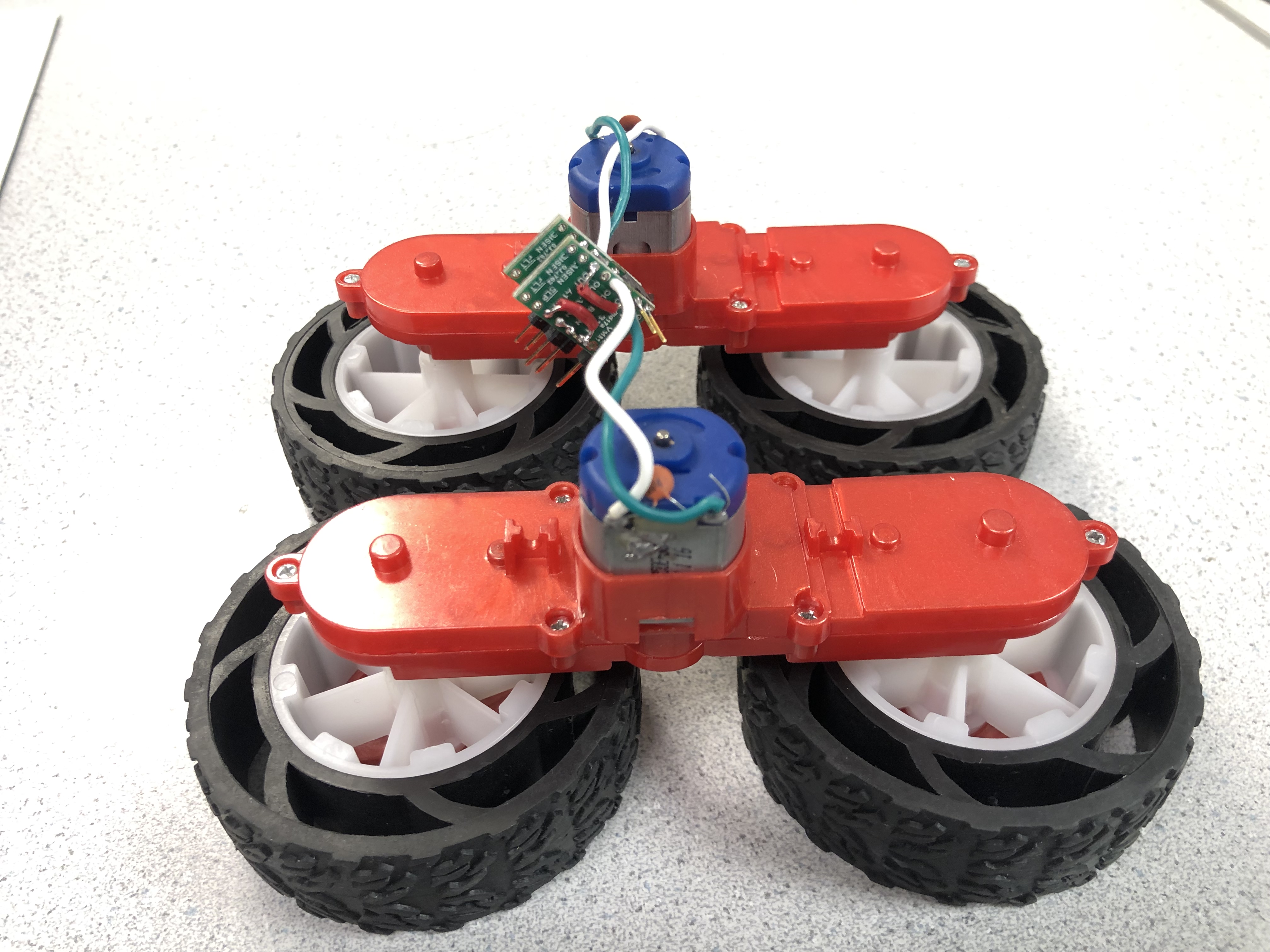
First, I solder AIN1 to BIN1, AIN2 to BIN2, AOUT1 to BOUT1, AOUT2 to BOUT2 for both motor drivers using wires.
Second, I solder AOUT1 and AOUT2 of one motor driver to one dc motor and the same for the other.
Third, I solder pins on AIN1 and AIN2 for both motor drivers so that they can connect to pins on Artemis Board using wires.
Fourth, I solder the VIN and GND pins of the two motor drivers together so that I can use only one wire to power them together.
Finally, I will choose pin A0, A1, A2, A3 on Artemis Board to control the two motor drivers because these pins can generate
analog signals which are what we need.
Performance Testing
First, I connect AIN1 and AIN2 of one motor driver to pin A0 and A1 of Artemis Board which is powered by a 850mAh battery,
and use the code below to control the motor driver. I set the duty cycle to be 255 which means the duty cycle is 100%, to find the working voltage range of the motor driver.
Second, I connect the VIN and GND to a power supply.
Finally, I adjust the voltage of the power supply from 0 to 5V to see the working current of the motor driver.
       void setup() {
            //activate the pins
            pinMode(A0, OUTPUT);
            pinMode(A1, OUTPUT);
            }

            void loop() {
            //send signals to motor drivers
            analogWrite(A0, 255);
            analogWrite(A1, 0);
            }
I adjust the votage from 0V to 5V and I find that we need a lower limit of about 2.55V to generate current for motor driver and about 2.7V to make the wheels spin, which coincides with the lowest operating voltage recorded in the documentation. And the minimum working current to make the wheel turn is about 0.35A. Then as I increase the voltage, the current also slowly rises, ranging from 0.35A to 0.5A. Under the rated working voltage of 3.7V, the rated working current is about 0.4A.
From the documentation, the duty cycle should be set ranging from 0 to 255 which means 0~100% of a cycle. Firstly, I set the duty cycle to be 255 which means 100% of a cycle. And from the video below we can know that the Artemis Board is generating a constant high level signal to the motor driver and the frequency is 0Hz.
Then I tired some other values of duty cycle and use a multimeter to measure rms. From the video below we can know that the analog signals generated by
the Artemis Board have a frequency of about 182Hz and the rms match the calculation of the duty cycle.
Duty cycle: 30 ; Val: 11.72% ~ 30/255;
Duty cycle: 100 ; Val: 39.09% ~ 100/255;
So from the data above we know how the motor drivers work:
Since we are using dc motors, it can only receive two commands: turn and not turn, but cannot control the speed and its voltage.
So we need to generate a analog signal to the motor driver to control the spinning speed. We can set a duty cycle 'dc' which corresponds to a percentage.
This means that in one cycle, the proportion of high level signal is 'dc', which also means the wheel spinning time is 'dc' in one cycle.
So when the frequency of the signal is high enough and the period is short enough, we can control the speed of motors very smoothly.
I change the direction of rotation of the motor by reversing the signal sent to the motor driver. Below are demo videos for the two motor drivers and motors.
I first put the car on a table and only activate one motor dirver once to measure the lower limit of duty cycle to make the car start.
From the demo videos for the two motor drivers, I find that the lower limit of duty cycle to make the car start is about 95 for one and 65 for the other,
which means that the two motors differ in their output power. However, this lower limit is also related to the battery voltage and power.
The more powerful the battery, the lower the lower limit.
From the test above we can know that the output power of the two motors is different under the same signal. But when the two motor drivers are connected together with the battery at the same time, their gap on output power is not as large as the previous experiment. I do find the motor on the left is a little bit stronger than the one on the right. When I set the duty cycle to be 65 for the left one and 67 for the right one, the car move along a fairly straight line. The calibration factor is about 65/67 = 0.97. Below is the demo video.
I design a loop for the car to make it go straight for a while and then turn around. So the car will move forth and back in a short distance.
The turning period should be related to the power of the battery and it is hard to decide.
So in subsequent labs, we still need to use the sensors to determine the rotation time to ensure the correct rotation angle.
Below is the demo video.
        #define fac 65.0/67.0;

        void setup() {
        //right
        pinMode(A0, OUTPUT);
        pinMode(A1, OUTPUT);
        //left
        pinMode(A2, OUTPUT);
        pinMode(A3, OUTPUT);
        }

        void loop() {
            analogWrite(A0, 67);
            analogWrite(A1, 0);
            analogWrite(A2, 0);
            analogWrite(A3, 65);
            delay(2000);
            analogWrite(A0, 255);
            analogWrite(A1, 0);
            analogWrite(A2, 255*fac);
            analogWrite(A3, 0);
            delay(200);
        }
5960 Tasks
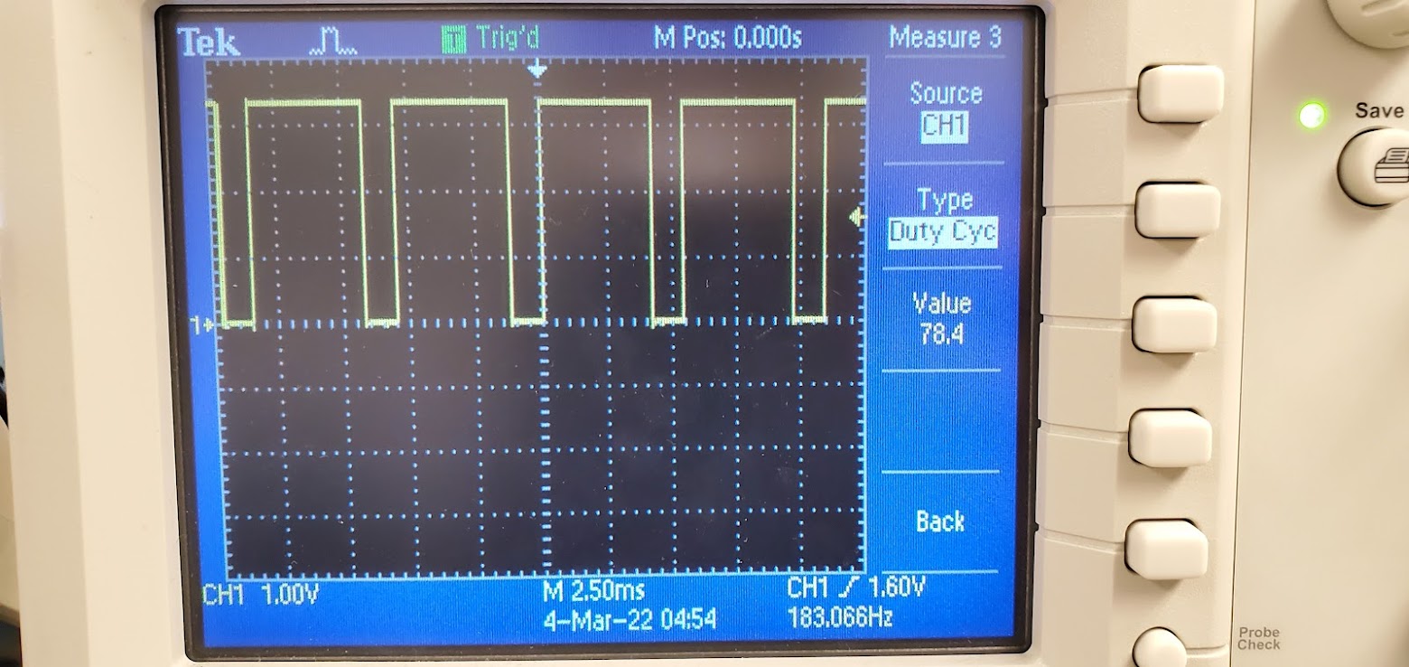
From the video above we know that the frequency of analog signals generated by the Artemis Board is about 182Hz when the duty cycle is lower than 255.
And it also can go up to about 183Hz when I reverse the output signals, but it's still relatively stable.
Since we adjust the speed of motors by changing the duty cycle, theoretically, the shorter the cycle, the smoother the signals and the better the motors move.
But it takes time for Artemis Board to pull the signal high and low, which is called 'rising edge' and 'falling edge', and the period should be
much larger than the time of 'rising edge' and 'falling edge' so that they can be ignored.
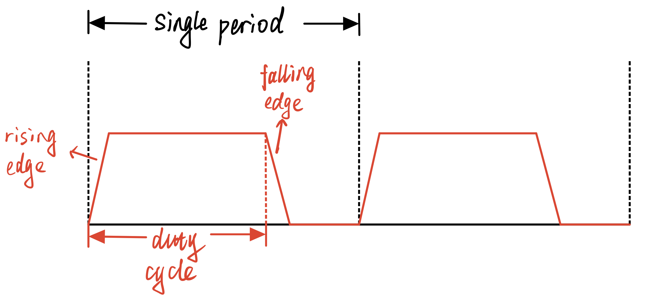
It can be seen from the waveform diagram of the oscilloscope that the rising and falling edges are almost a vertical line, so the period is large enough to ignore the time to pull signal high and low. But if we can make the period as small as possible (which means make the frequency as large as possible) while keeping it much larger than the time of 'rising edge' and 'falling edge', then we will be able to control the speed of the car more smoothly.
I design a program to make the car speed up slowly to maximum for a while and then speed down quickly to avoid hitting the wall, and use notify function to receive the dc value sent by Artemis Board in the meantime.
In loop function
        while (central.connected()) {

            if(state==0 && dc+15<=255) dc += 15;
            else if(dc-51>=0) dc -= 51;

            if(dc==255){
                state = 1;
                delay(300);
            }

            straight();
            get_val();}
Subfunctions:
        void straight(){
            analogWrite(A0, dc);
            analogWrite(A1, 0);
            analogWrite(A2, 0);
            analogWrite(A3, dc);
            }

        void get_val(){
            tx_float_value = dc;
            tx_characteristic_float.writeValue(tx_float_value);
            }
Notify function:

To get the speed of the car:
Firstly, I hook up all the sensors on the car and connect them to the Artemis Board and activate one ToF at the front of the car to get the distance from the wall.
Secondly, I design a program which will make the car speed up slowly to maximum and keep running until receiving 'stop' command.
When the Artemis Board is connected to the computer via bluetooth, the car will first wait for 10s and then start.
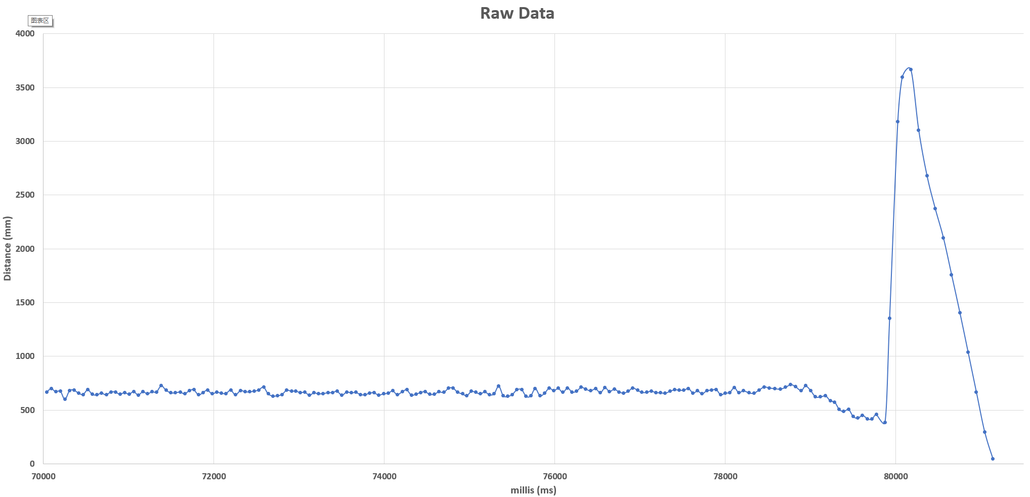
Thirdly, I activate a notify function in Jupyter Lab to receive data read by ToF so that I can then calculate the maximum speed of the car.
        int t_0 = millis();
        // While central is connected

        while (central.connected()) {

            if(millis()-t_0>10000 dc+15<=255) dc += 15;

            straight();
            get_tof();}
Subfunctions:
        void get_tof()
        {
            distanceSensor.startRanging(); //Write configuration bytes to initiate measurement
            while (!distanceSensor.checkForDataReady())
            {
            delay(1);
            }
            int distance = distanceSensor.getDistance(); //Get the result of the measurement from the sensor
            distanceSensor.clearInterrupt();
            distanceSensor.stopRanging();

            Serial.println(distance);


            tx_estring_value.clear();
            tx_estring_value.append("[");
            tx_estring_value.append((float)millis());
            tx_estring_value.append(", ");
            tx_estring_value.append(distance);
            tx_estring_value.append("]");
            tx_characteristic_string.writeValue(tx_estring_value.c_str());
        }
Notify function:

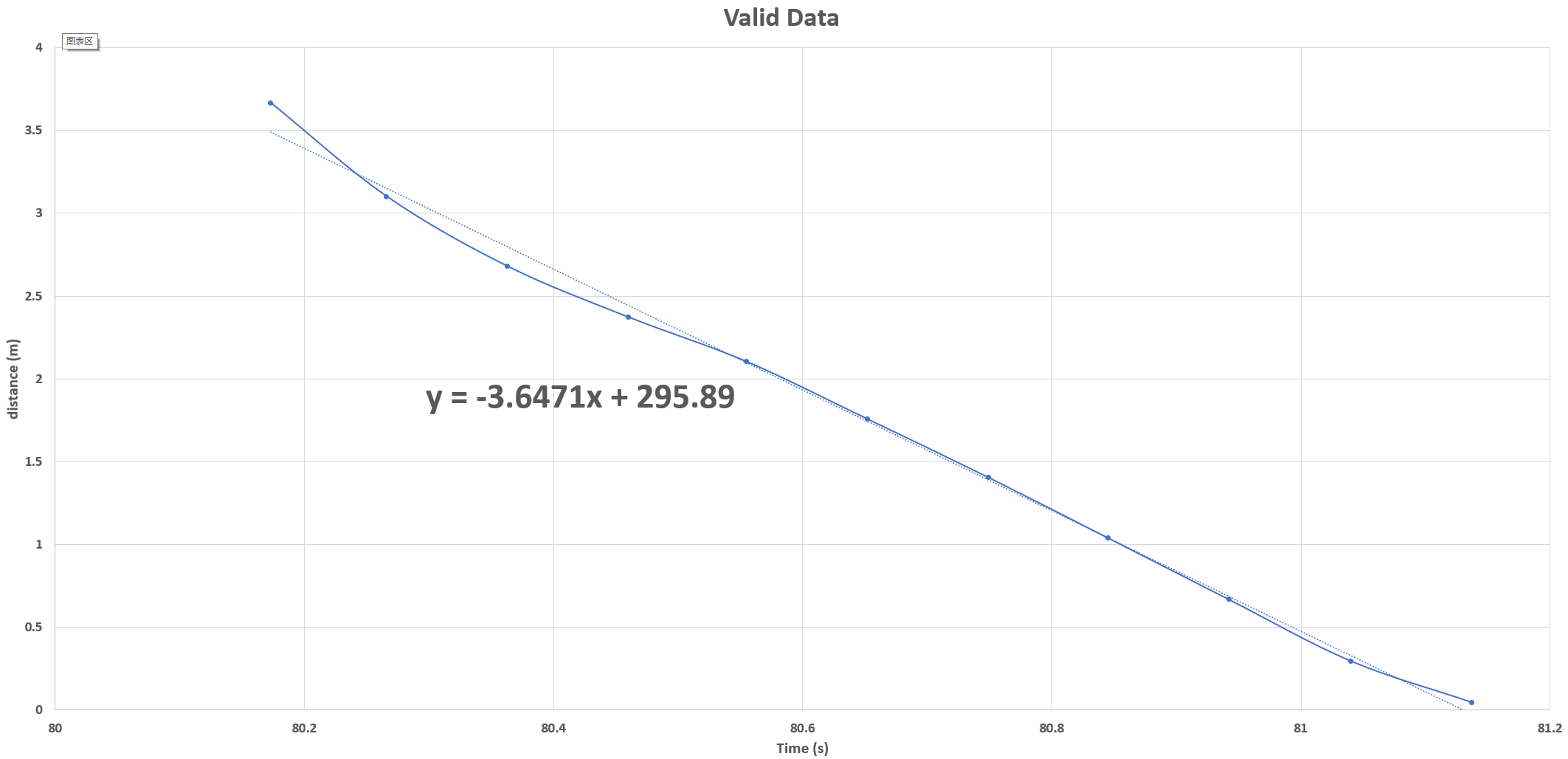
Having collected the data from Jupyter Lab, I eliminated the invalid data and calculated the maximum running speed of the car from the valid data.
From the diagram below we can know that the maximum speed of the car is about 3.65m/s. As the minimum speed is 0, the range of speed is 0~3.65m/s.
