LAB 12 - Grid Localization (Real)
Objective
The goal of this lab is implementing and performing localization on the actual robot car using only the update step of the Bayes filter.
Simulation
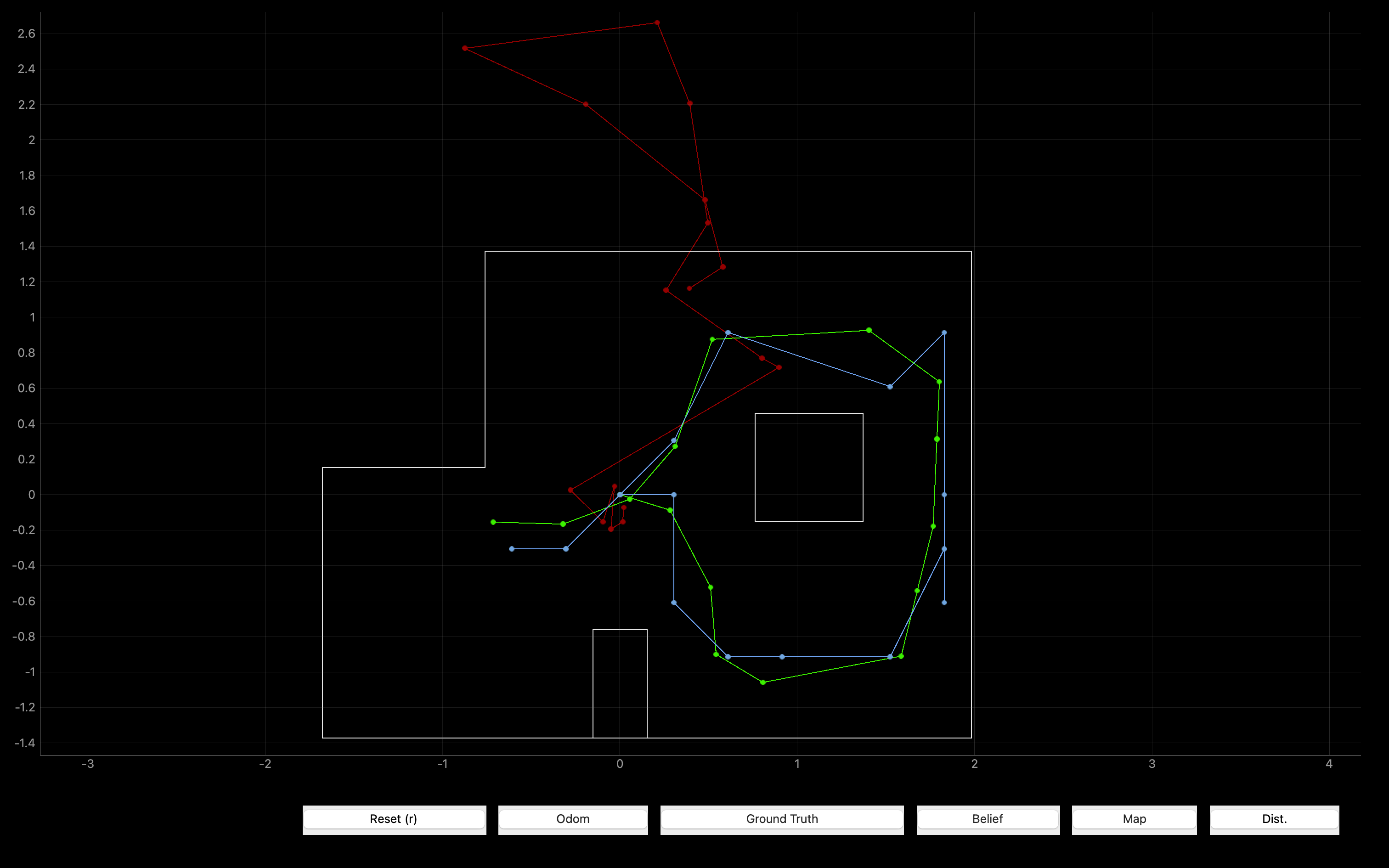
Before implementing the function on the actual robot car, we need to test the code by simulation in Jupyter Lab to make sure that the code is functionally free of problems and bugs:

By comparing the trajectories of Ground Truth and Belief, it can be found that the function of the code is intact and can be used for actual robot.
Localization
To implement the update step of Bayes filter, we need to Perform the observation loop behavior on the real robot car, where the robot does
a 360 degree turn in place while collecting equidistant (in the angular space) ToF sensor
readings, with the first sensor reading taken at the robot's current heading.
From Lab 11 we can know that the robot need to collect ToF sensor reading every 20 degree in one turn. So I just take use of the
PID control implemented in Lab 9, and then change the rotation and data collection interval from 10° to 20° so that the robot collects
18 ToF sensor readings corresponding to the rotation angle in one turn. (refer Lab 9 and Lab 11.)
Below is the demo video while deploying the car on the set point with fixed initial heading (to the right of the map, that is, the positive direction of the x-axis):
In this part, I send commands (including performing the turn while collecting data and transfering the data to computer) to the robot by BLE communication.
For performing the turn while collecting the data, I just need to send the corresponding command (LAB) and wait for it to complete (time.sleep()) since the whole function is already written into the Artemis Board.
        #Make the car to do a 360-degree rotation while storing the data needed
        ble.send_command(CMD.LAB, "")
        time.sleep(40)
For getting the data from the car:
First, I use a notify function called update
to monitor whether the corresponding value (RX_STRING) on the Artemis Board has changed.
The function is able to detect and record the value whenever it changes;
Second, I send a command (GET_DATA) to the robot to make the robot sequentially
write the data collected into the corresponding value (RX_STRING),
which can be notified by the computer and recorded into an empty array raw.
Finally, I separate the data in raw and store them in corresponding arrays
(sensor_ranges and sensor_bearings) respectively,
which will be used to calculate the belief of the robot.
        #Transfer the data to computer and store it properly
        ble.start_notify(ble.uuid['RX_STRING'], self.update)
        time.sleep(2)
        ble.send_command(CMD.GET_DATA, "")
        time.sleep(2)
        ble.stop_notify(ble.uuid['RX_STRING'])

        #Seperate the data
        for i in range(36) :
            if(i%2==0):
                sensor_bearings.append(self.raw[i])
            else:
                sensor_ranges.append(self.raw[i]/1000)

        #Transpose matrix
        sensor_ranges = np.array(sensor_ranges)[np.newaxis].T
        sensor_bearings = np.array(sensor_bearings)[np.newaxis].T

        #update function for notify
        def update(self,raw,b):
        #Store the data into raw
            temp = ble.bytearray_to_float(b)
            self.raw.append(temp)
Result
The following are the localization results of the robot at the required four points (the position where the x-y axis crosses is (0,0)):
For each point I tested twice.
Result 1: (-3,-1)
_v1_res.png)
_v1_polar.png)
_v1_1.png)
_v1_2.png)
Result 2: (-3,-2)
_v2_res.png)
_v2_polar.png)
_v2_1.png)
_v2_2.png)
Result 1: (-1,3)
_v1_res.png)
_v1_polar.png)
_v1_1.png)
_v1_2.png)
Result 2: (0,3)
_v2_res.png)
_v2_polar.png)
_v2_1.png)
_v2_2.png)
Result 1: (5,2)
_v1_res.png)
_v1_polar.png)
_v1_1.png)
_v1_2.png)
Result 2: (5,3)
_v2_res.png)
_v2_polar.png)
_v2_1.png)
_v2_2.png)
Result 1: (5,-3)
_v1_res.png)
_v1_polar.png)
_v1_1.png)
_v1_2.png)
Result 2: (5,-3)
_v2_res.png)
_v2_polar.png)
_v2_1.png)
_v2_2.png)
Discussion
From the result above, we can find that most of the localized poses are very close to (only one grid error)
or just right at the Ground Truth.
According to the error analysis in LAB 9, I think one of the reasons for the deviation is
the deviation of the actual rotation center from the theoretical center,
which can be seen in the demo video.
Due to the uneven ground friction,
the natural inclination of the ground,
and the inconsistency of the tire rotation speed, etc.,
it may cause the rotation center of the car to gradually deviate from the original one during the rotation process,
and eventually cause the position of the car to deviate from the original placement position after a 360 degree turn.
On the other hand, topographical factor may more or less cause the deviation for the three points.
At these points, the car need to detect some relatively difficult points
(obstacles's edge or distant wall),
which can easily lead to larger error.
All in all, edges that are far away and
edges whose distance varies greatly with angle are prone to larger errors.
If the position of localization deviates greatly from Ground Truth during the experiment, the reason is mostly because the ToF reading has a large error (out of range or just an occasional reading error), or you forgot to convert the ToF readings(mm) into the unit read by the function(m).
In addition, I found that the localization at point (5,3) is relatively more accurate.
From the polar coordinate results of the two experiments, it can be found that the data of the two experiments are highly consistent,
which indicates that the ToF readings of the two experiments are very stable and consistent.
This may be because the position of point (5,3) faces the wall very close on two sides (right and below),
and the distances of the obstacles on the left and the upper left are relatively closer, which reduces the probability of a large ToF error.