LAB 3 - Sensors
Wiring
In this part, I just imitated the example robot showed by TA to wire all the parts together:
1. Connect the Artemis Board to one ToF
2. Connect the ToF to IMU
3. Connect the IMU to the other ToF
In addition, I also connect xshuts of the ToFs to wires with a female header for changing their address.
So my layout of sensors will be the same as the example car:
1. The Artemis Board will be put in the place of the original controlling chip;
2. The ToF that is beside the Artemis Board will be placed on one side of the cart;
3. The IMU will be placed on the surface of battery pack;
4. The other remote ToF will be placed on the front of the car.
Avalibility
For the case that only one ToF is connected, I firstly scanned the I2C channel and found that the ToF is at address 0x29:
Then I tested the default mode of the ToF:
After wiring all the parts together, I tested the functionality of IMU and Tof separately. Before testing, I manually set the addresses of the two ToFs respectively through xshut to ensure they work corretly.
    //Optional interrupt and shutdown pins.

    #define SHUTDOWN_PIN0 0
    #define SHUTDOWN_PIN1 1

    #define INTERRUPT_PIN 3


    SFEVL53L1X distanceSensor0;
    SFEVL53L1X distanceSensor1;

    //Uncomment the following line to use the optional shutdown and interrupt pins.
    //SFEVL53L1X distanceSensor(Wire, SHUTDOWN_PIN, INTERRUPT_PIN);

    void setup(void)
    {
        Wire.begin();

        Serial.begin(115200);

        pinMode(SHUTDOWN_PIN0, OUTPUT);
        pinMode(SHUTDOWN_PIN1, OUTPUT)
        Serial.println("VL53L1X Qwiic Test");

        digitalWrite(SHUTDOWN_PIN0, LOW);
        digitalWrite(SHUTDOWN_PIN1, LOW);

        delay(50);
        digitalWrite(SHUTDOWN_PIN0, HIGH);
        delay(50);

        if (distanceSensor0.begin() != 0) //Begin returns 0 on a good init
        {
        Serial.println("Sensor0 failed to begin. Please check wiring. Freezing...");
        }

        else{
        distanceSensor0.setI2CAddress(0x29);
        }
        //Serial.printf("port: 0x%08X\n", (uint32_t)distanceSensor0.getI2CAddress());
        Serial.println("Sensor0 online!");


        delay(50);
        digitalWrite(SHUTDOWN_PIN1, HIGH);
        delay(50);
        if (distanceSensor1.begin() != 0) //Begin returns 0 on a good init
        {
        Serial.println("Sensor1 failed to begin. Please check wiring. Freezing...");
        }

        else{
        distanceSensor1.setI2CAddress(0x30);
        }
        Serial.println("Sensor1 online!");
    }

    void loop(void)
    {
        distanceSensor0.startRanging(); //Write configuration bytes to initiate measurement
        while (!distanceSensor0.checkForDataReady())
        {
        delay(1);
        }
        int distance0 = distanceSensor0.getDistance(); //Get the result of the measurement from the sensor
        distanceSensor0.clearInterrupt();
        distanceSensor0.stopRanging();

        distanceSensor1.startRanging(); //Write configuration bytes to initiate measurement
        while (!distanceSensor1.checkForDataReady())
        {
        delay(1);
        }
        int distance1 = distanceSensor1.getDistance(); //Get the result of the measurement from the sensor
        distanceSensor1.clearInterrupt();
        distanceSensor1.stopRanging();

        Serial.print("Distance0(mm): ");
        Serial.print(distance0);

        float distanceInches0 = distance0 * 0.0393701;
        float distanceFeet0 = distanceInches0 / 12.0;

        Serial.print("\tDistance0(ft): ");
        Serial.print(distanceFeet0, 2);

        Serial.print(" || ");

        Serial.print("Distance1(mm): ");
        Serial.print(distance1);

        float distanceInches1 = distance1 * 0.0393701;
        float distanceFeet1 = distanceInches1 / 12.0;

        Serial.print("\tDistance1(ft): ");
        Serial.print(distanceFeet1, 2);


        Serial.println();
    }
I first initialized the ToFs' xshuts to be 'LOW'. And then manually set their address via digitalWriting the xshuts to be "HIGH" one after another. And I found that only when one of them has been set to a certain address, can I then digitalWrite the other's xshut to 'HIGH' and set the address for it. Otherwise one of them will not be detected, which means they may conflict in the same address.
Then I tested the function of IMU. Before using Example1_Basics to test the IMU, I set the "AD0_VAL" to be "0", which means that the value of the last bit of IMU's I2C address is "0". Because the initial address of the IMU is 0x68, whose last bit in binary is "0".
So far, I had confirmed that all the parts wired together were working well.
ToF
Before starting the test, I set one of the ToFs to be short-distance-mode while the other is long-distance-mode. (The mideium-distance-mode can not be recognized by the App)
    if (distanceSensor0.begin() != 0) //Begin returns 0 on a good init
    {
        Serial.println("Sensor0 failed to begin. Please check wiring. Freezing...");
    }
    else{
        distanceSensor0.setI2CAddress(0x29);
        distanceSensor0.setDistanceModeShort();
    }
    //Serial.printf("port: 0x%08X\n", (uint32_t)distanceSensor0.getI2CAddress());
    Serial.println("Sensor0 online!");


    delay(50);
    digitalWrite(SHUTDOWN_PIN1, HIGH);
    delay(50);
    if (distanceSensor1.begin() != 0) //Begin returns 0 on a good init
    {
        Serial.println("Sensor1 failed to begin. Please check wiring. Freezing...");
    }
    else{
        distanceSensor1.setI2CAddress(0x30);
        distanceSensor1.setDistanceModeLong();
    }
Together with Yingjie Zhao, I lay the equipments for measuring tof accuracy on the ToF.
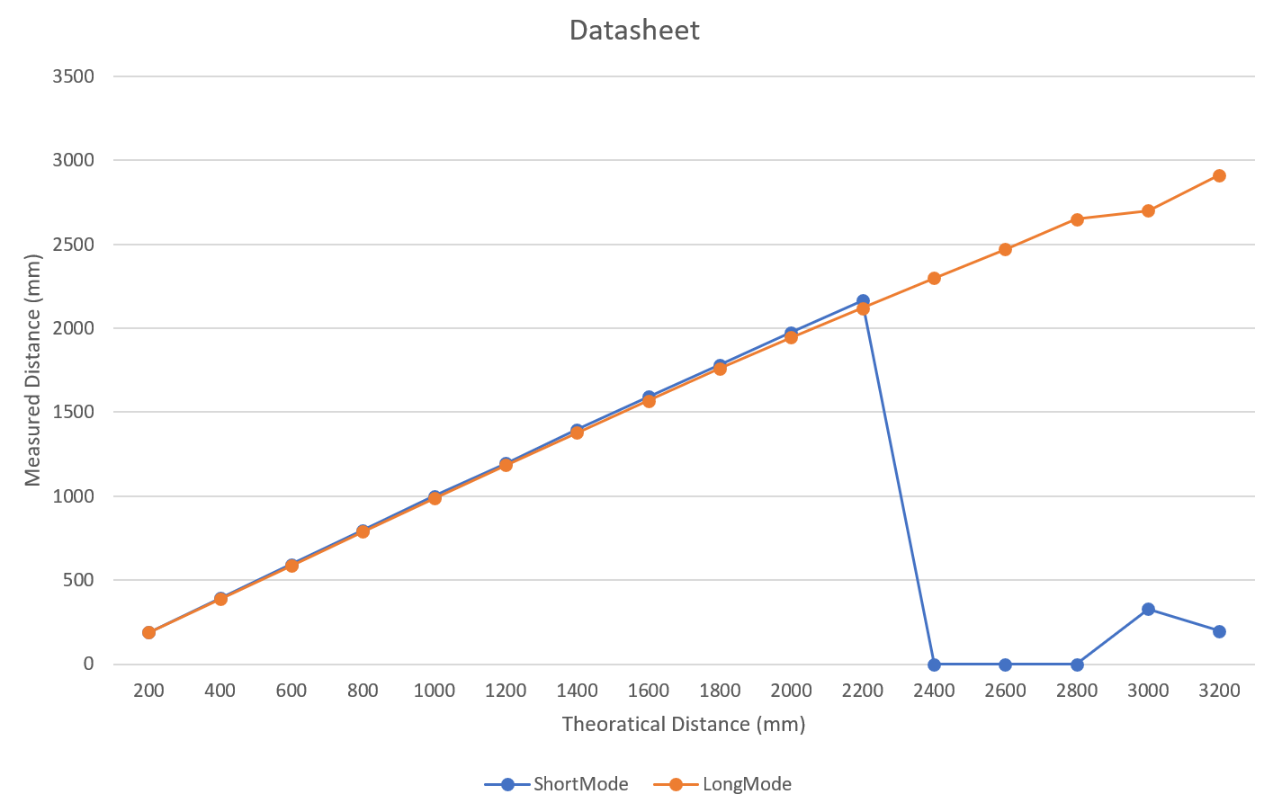
Then we record the data every 20cm from the ToFs to see their linearity:


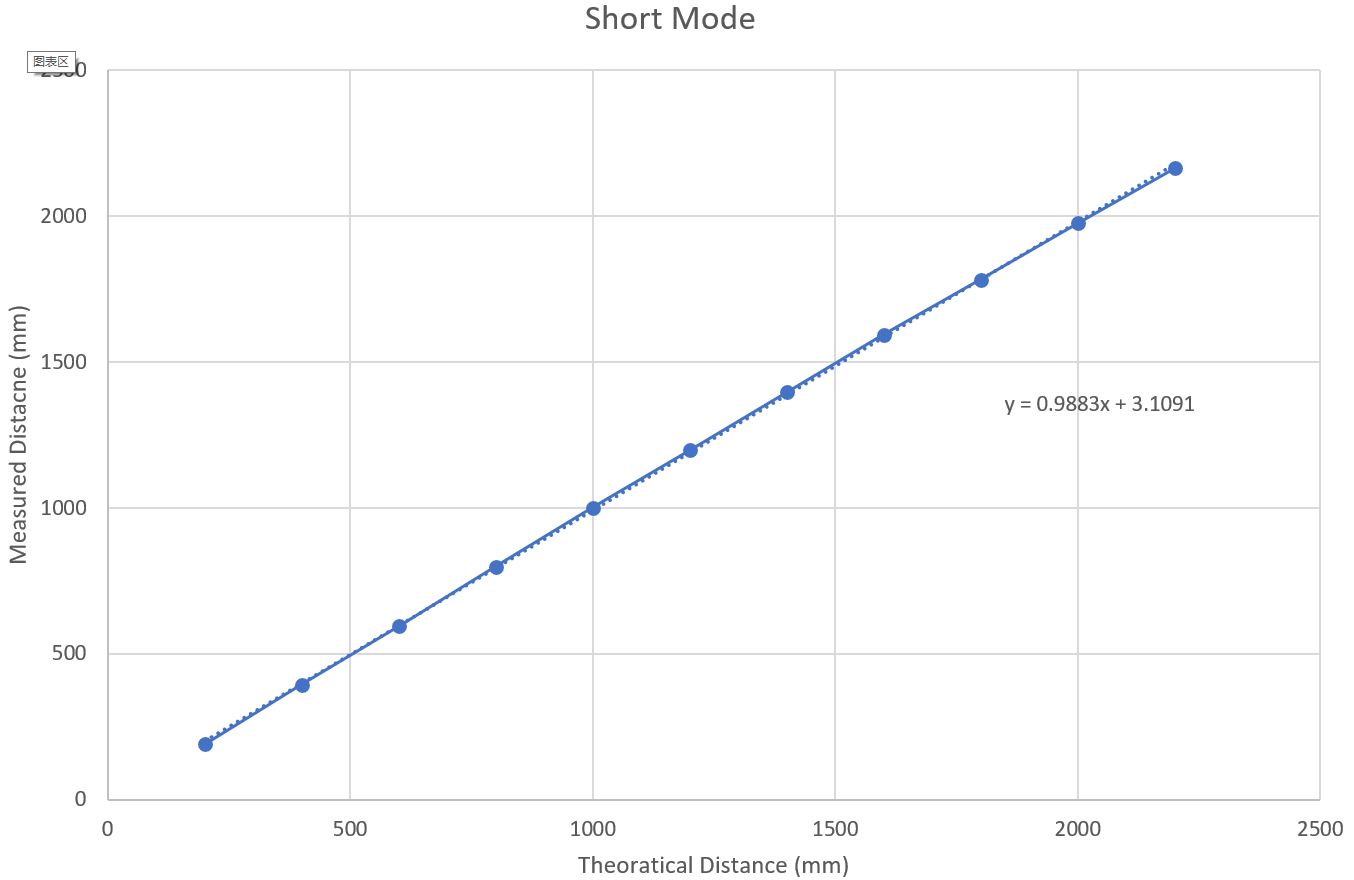
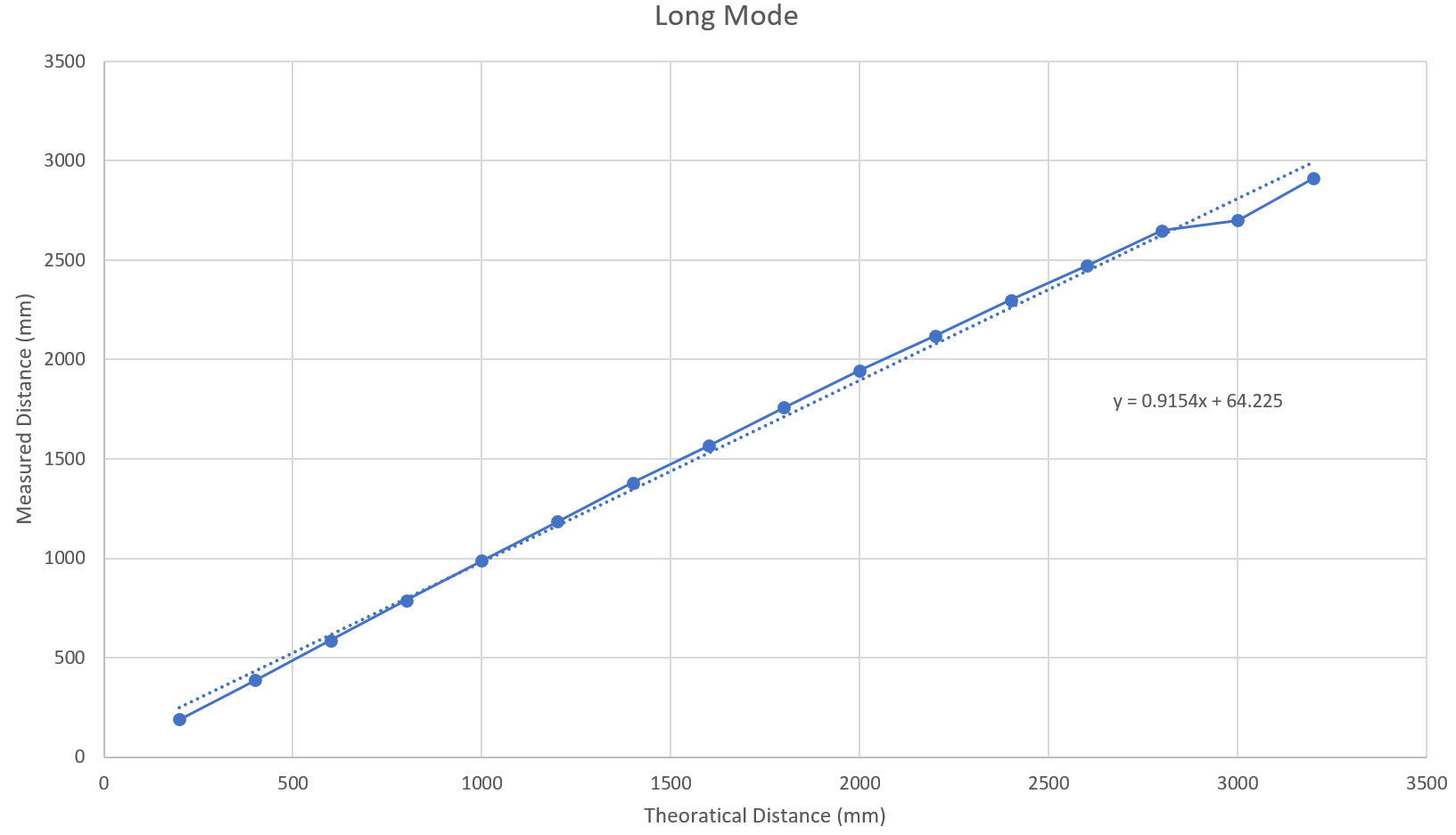
From the data, we can see that the short distance mode is more accurate because the wavelength of infrared emitted in this mode is shorter and it takes less time to process the data.
But at the same time, its range is shorter, who loses its reliability at about 2.2m. On the other hand, the long distance mode has a larger range but worse error.
In the data, we can see that the conversion factors for these two modes are 1/0.9883 and 1/0.9154.
However, even in long distance mode, we cannot measure its theoretical maximum range (4m). The maximum measurable value is about 3.2m.
There are only several legal values for Timing Budget: 20, 33, 50, 100. As I am building a fast robots, I should make the Timing Budget be as fast as possible. So I choose 20ms to be the Timing Budget and then I tested sevearl different
values of Intermeasurement Period from 20ms to 100ms. (If I set the Timing Budget to be higher, there will be more signal fails)
After many attempts, I discovered a law how the Artemis Board run in the loop:
Actual operating cycle = Intermeasurement Period - 10
Which means if I set the Intermeasurement Period to be 50ms, the time for one loop is 40ms and the frequency is 25Hz, which is very interesting!
And as the frequency goes larger, the probability of running failure is also getting lower and lower (When the History_Size is set).
When I set the Intermeasurement Period to be 30ms (The frequency is 50hz), the sensor can always run in good condition even I change the distance from the sensor to an object rapidly.
In the future, I will tested the car in different frequency to find a mode that minimize the occurence of any kind of fails.
IMU
Accelerometer
Having set up the IMU and activated the accelerometer, the IMU is able to obtain data in three directions of x,y, and z. Then I add codes showed below to convert accelerometer data into pitch and roll:
    float roll = 180 * atan2(sensor->accY(),sensor->accZ())/M_PI;
    float pitch = 180 * atan2(sensor->accX(),sensor->accZ())/M_PI;
    SERIAL_PORT.print("roll: ");
    printFormattedFloat(roll, 3, 2);
    SERIAL_PORT.print(", ");
    SERIAL_PORT.print("pitch: ");
    printFormattedFloat(pitch, 3, 2);
Then I recorded the output at {-90, 0, 90} degrees pitch and roll using the app called "spirit level" in iphone as a benchmark. I found the horizontal (0°) measurement is accurate. But the output at 90° or -90° are 88° and -88°, which needs a two point calibration. And the conversion factor is (180 / 176 = 1.0227).
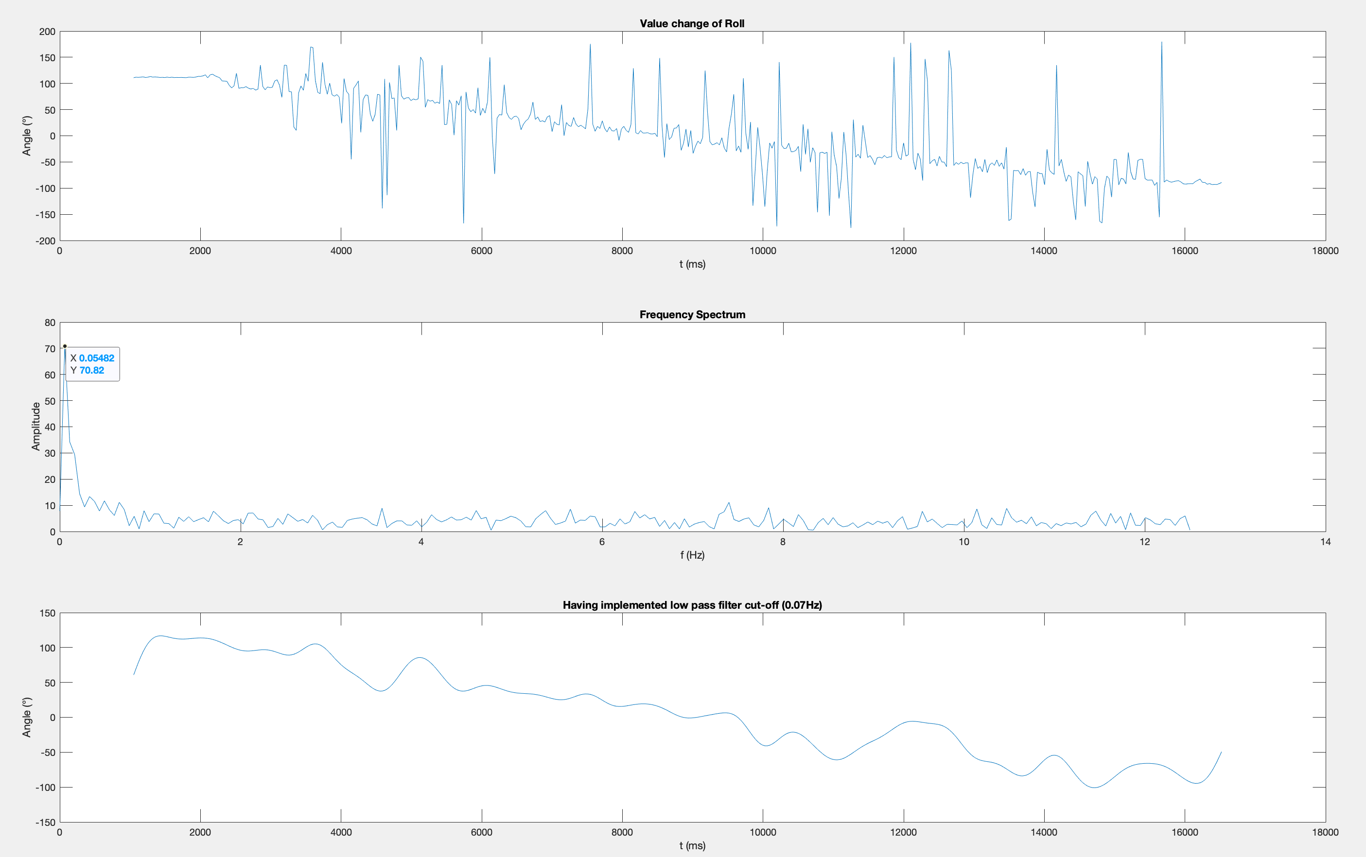
In this part, I slowly roll the IMU while tapping it continuously and record the data of angle of roll. Then I put the data into MATLAB and calculate the frequency spectrum using Fourier Transform. I found that the frequency of my rolling is 0.05482Hz and others are all "unwanted noises". So I implemented complimentary low pass filter cut off frequency at 0.07Hz.

Having filted the "unwanted noises", the plot becomes a lot smoother, which can better show the correct trends of roll.
Gyroscope
I use the equations from slides to calculate pitch, roll, and yaw angles using data from the gyroscope. I set the default value of roll_g and pitch_g to be the first data calculated from accelerometer because the gyroscope doesn't have a default value.
        dt = millis() - last;
        last += dt;
        roll_g +=  sensor->gyrX() * dt / 1000;
        pitch_g -= sensor->gyrY() * dt / 1000;
        yaw_g -= sensor->gyrZ() * dt / 1000;

        SERIAL_PORT.print("||");
        SERIAL_PORT.print("roll_g: ");
        printFormattedFloat(roll_g, 3, 2);
        SERIAL_PORT.print(", ");
        SERIAL_PORT.print("pitch_g: ");
        printFormattedFloat(pitch_g, 3, 2);
        SERIAL_PORT.print(", ");
        SERIAL_PORT.print("yaw_g: ");
        printFormattedFloat(yaw_g, 3, 2);
Through the observation and analysis of the data, I found that the gyroscope is unstable even if I put it on a stable table. The value of roll and pitch increase continuously at standstill, and the zero points are very sensitive to rapid vibrations. When the IMU is stable, its accuracy is far less than accelerometer.
Then I use a complimentary filter (alpha = 0.5) to compute an estimate of pitch and roll which is not susceptible to drift or quick vibrations: (The black line is the complimentary one)
    float roll_c = roll * alpha + roll_g * (1-alpha);
    float pitch_c = pitch * alpha + pitch_g * (1-alpha);
Magnetometer
I use the code below to calculate yaw angle using data from magnetometer and accelerometer.
    float xm = sensor->magX()*cos(pitch) - sensor->magY()*sin(roll)*sin(pitch)
               + sensor->magZ()*cos(roll)*sin(pitch);
    float ym = sensor->magX()*cos(roll) + sensor->magZ()*sin(roll/180*M_PI);
    float yaw = 180 * atan2(ym, xm)/M_PI;
Since the zero point of magnetometer is not exactly 0, I first place IMU horizontally, and then rotate it 360 degrees along the z-axis to observe the value changes of magX. When the value goes to minimum point, the orientation where the x-axis points to is the magnetic north (which is also the soulth pole).
From the video above, I found that the yaw angle fluctuates widely and rapidly, which is not robust at all.